Building a Drawing Robot (and Getting a 3D-Printing Education Along the Way)
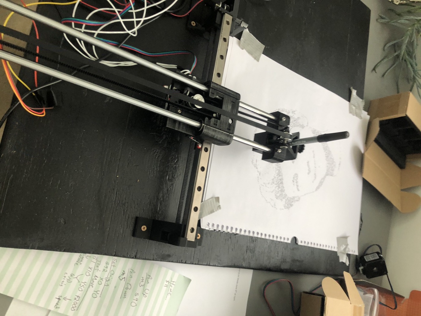
Back in 2021 I came across a YouTube build from the DIY Machines channel — Super Easy 3D Printed Arduino CNC Drawing Machine — a pen plotter with every structural part 3D printed, riding on smooth rods and stepper motors. (“Super easy” is doing some heavy lifting in that title, as we’ll see.) The best way I can describe the machine is that it’s a 3D printer that lost an axis. Two steppers move a gantry in X and Y, exactly like a printer moves its hot end — but instead of a nozzle extruding plastic layer by layer, there’s a ballpoint pen in a printed clamp, and instead of a Z axis there’s a tiny servo that tips the pen onto the paper or lifts it off. Down, draw, up, move, repeat.
I built it. It eventually worked, and worked well — but “eventually” is the part worth writing about, because this project had two distinct educations in it: one in making the parts, and one in making them move.
Education one: earning the parts
The bill of materials assumes you can just print the twenty-odd structural pieces — motor mounts, rod holders, the pen carriage, belt clamps. What that assumption concealed, for me, was that I had to learn to 3D print reliably before I could build a robot at all. The plotter came with a 3D-printing apprenticeship attached.
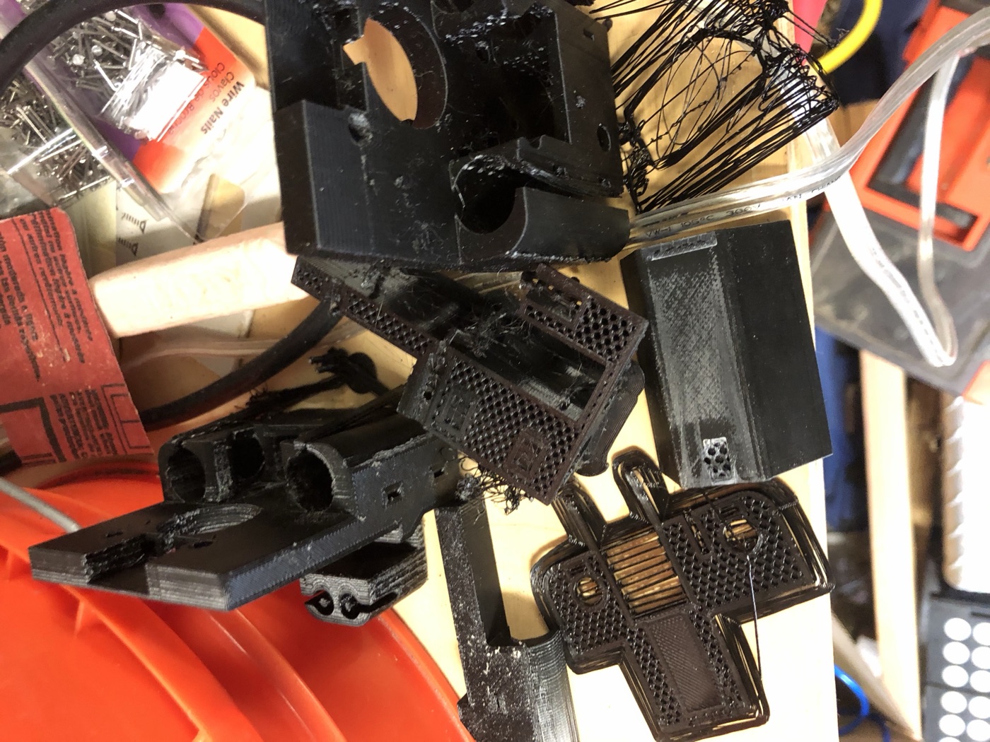
I accumulated a full bin of failures and do-overs: warped bases, layers that parted mid-print, and — the classic — prints that turned into “spaghetti” when a corner came unstuck and the printer kept cheerfully extruding into the air:
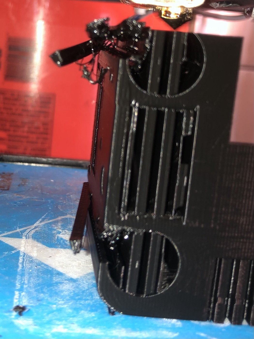
The recurring villain was the nozzle. Clogs and partial clogs produced under-extruded, brittle parts, and I got a lot of unplanned practice disassembling the print head to clean or replace the nozzle — the kind of maintenance nobody’s build video budget includes. None of this was wasted: every structural part in the final machine is a part I printed after I understood bed adhesion, temperatures, and what a healthy first layer looks like. But if you’re following a build like this, multiply the printing timeline by three and consider the failures tuition. (The printer, for the record: a Flashforge Finder — a perfectly friendly machine once I learned to stop mistreating its nozzle.)
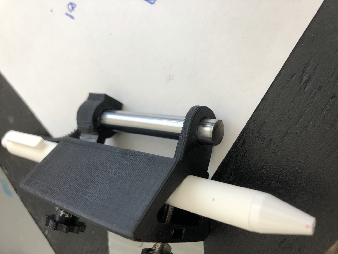
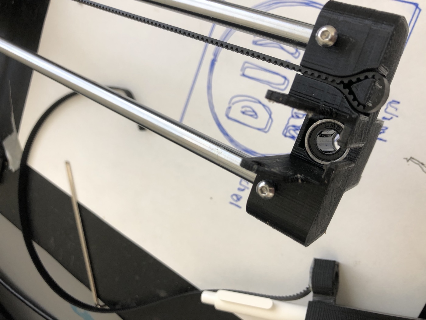
The parts themselves, once printed well, are genuinely satisfying — snug LM8UU bearing pockets, integrated clamps for the GT2 timing belts, a pen holder with a thumbscrew so any pen or marker can be swapped in:
Education two: making it move
The electronics are the standard hobby-CNC stack: an Arduino wearing a CNC shield with stepper drivers, one stepper per axis, and a small hobby servo for the pen lift. The whole thing mounts to a plywood board (mine got a coat of black paint and a lot of duct tape holding paper down).
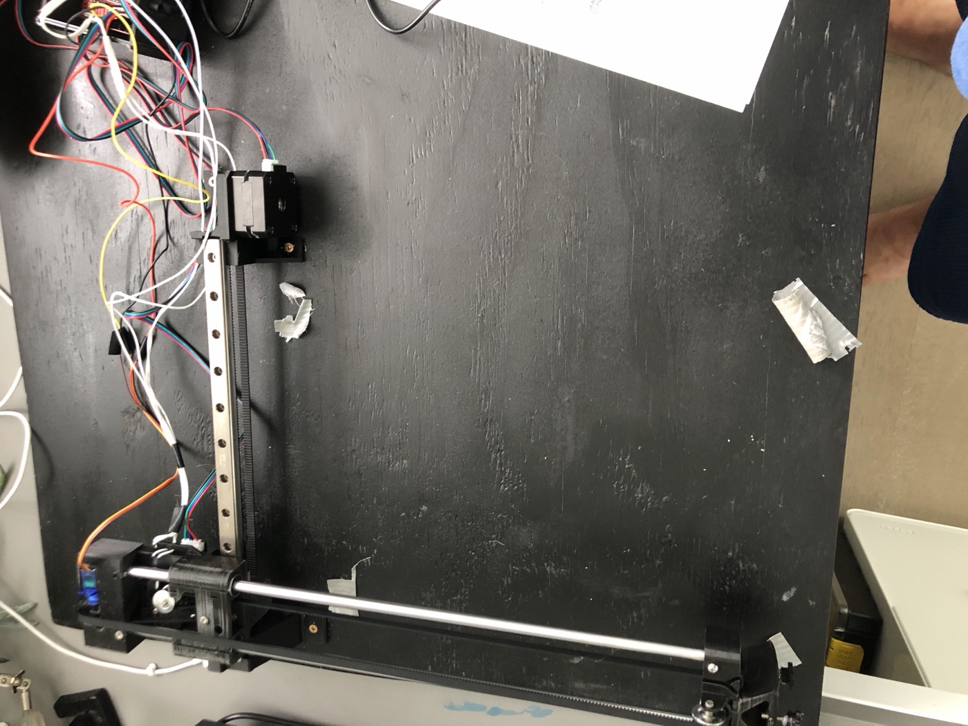
The controller runs GRBL, the open-source firmware that turns an Arduino into a G-code interpreter — specifically the lightly modified build that ships with the project’s companion repo, tweaked so the servo pen-lift answers to spindle commands. And this is where the “3D printer minus an axis” framing pays off practically: the robot speaks the same language as every 3D printer and CNC machine — G-code, the decades-old numerical-control dialect. There’s something pleasing about driving a 2021 pile of printed plastic with commands standardized when the cutting-edge output device was a milling machine.
My entire command vocabulary fit on a sticky note that lived next to the machine (you can spot it in the header photo):
$H                  ; home
M3 S90              ; pen up   (servo swings the pen off the paper)
M5                  ; pen down
G92 X0 Y0           ; call this spot the origin
G1 X10 Y50 F2000    ; move to (10, 50) at feed rate 2000
That’s it. Everything the robot ever does is a long sequence of those five ideas.
Upstream of the firmware, the drawings themselves start life as vector art: the project provides an Inkscape extension that converts paths into G-code, so anything you can express as lines in a vector editor — traced photos, contour data, even text — becomes something the robot can draw.
The software layer didn’t work for me straight out of the box — this is where the project’s “bit of tweaking” lived, and I remember an evening or two of fiddling before the first clean drawing. The details are on some retired laptop; if anyone’s curious enough to ask, I can probably dig them up.
What it drew
Two outputs I kept, and they show off opposite ends of what a pen plotter is good at.
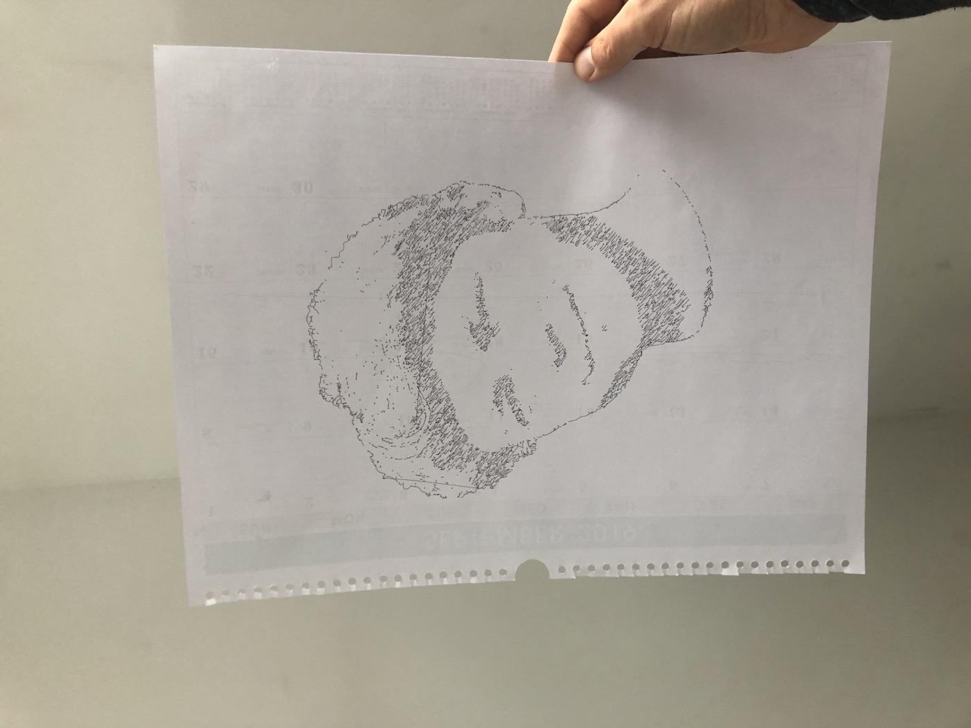
The first: portraits, rendered not as pixels but as a single wandering, scribbling line — dense hatching where the source photo is dark, open paper where it’s light. Watching it work is hypnotic, because unlike an inkjet the machine draws the way a person might, one continuous gesture at a time. (The canvas, in the finest tradition of home engineering, is the back of a 2019 wall calendar.)
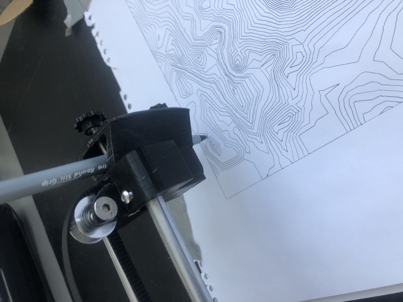
The second: contour maps. Elevation data traced as nested topographic lines — this one is Mount Saint Helens, crater and all, with the title lettering also plotted:
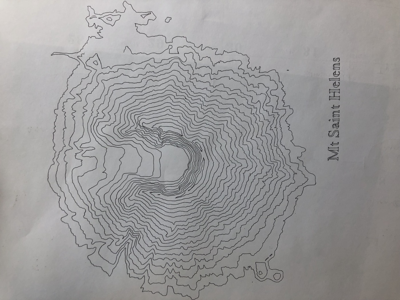
Readers of the canoe-maps post will detect a theme: apparently any project I touch eventually produces a topographic map. In my defense, contour lines are the perfect pen-plotter subject — long continuous paths, no fills, and the physical pen gives them a hand-drawn warmth that a printed map doesn’t have.
What stuck with me
A drawing robot is close to the ideal first machine-building project, and not because the result is useful — it decidedly isn’t. It’s that the project sits at exactly the right level of abstraction-piercing. Above it: G-code, firmware, toolpaths — the software stack every fabrication machine uses, learnable here with a $2 pen instead of a $200 spindle. Below it: belts, bearings, steppers losing steps, servos twitching — the physical reasons the software abstractions exist. And beside it, in my case, the involuntary 3D-printing course, which turned the printer from an appliance into a machine I understood and could fix.
Every mistake cost a sheet of paper. That’s the whole tuition schedule, and I recommend it.